Das vorliegende Arduino-Projekt ist eine Kombination aus mindestens zwei vorangehenden Projekten, nämlich jenem über das 4 digit 7 segment LED Display und jenem über Arduino als Uhr. Neu hinzugekommen ist eine echte Real Time Clock, d.h. eine RTC-Komponente mit Stützbatterie, so dass die Uhrzeit, wenn sie einmal gesetzt ist, erhalten bleibt, auch wenn man den Arduino von der Stromversorgung abhängt.
Projektziel
Anzeige der von einer RTC-Komponente gelieferten Uhrzeit auf einem multiplexed 4 digit 7 segment LED-Display.
Komponenten
Die Komponenten bestehen aus den gleichen Komponenten wie das LED-Display-Projekt sowie einem RTC-Modul.
- 1 Arduino UNO R3
- 1 Steckbrett
- 1 multiplexed 4-Digit-7-Segment LED Display LN3461AS2B, common cathode, 12 Pins (Bezugsquelle Schweiz, Datenblatt)
- 4 Widerstände 680 Ohm
- 12 Jumperkabel M/M
- 4 Jumperkabel M/F
- Stiftleiste 7 Pin einfach
- ein paar Drahtverbindungen, damit das Display im Kabelsalat nicht total verschwindet
- RTC-Modul DS1307, konkret ein DS1307 und AT 24C32 Combo Breakout (Bezugsquelle Schweiz, Datenblatt)
Und wenn man nicht die Stiftleiste ständig gegen das RTC-Modul drücken will, dann benötigt man
- Lötkolben oder Lötstation
- Lötzinn
Bestückungsplan und Verkabelung
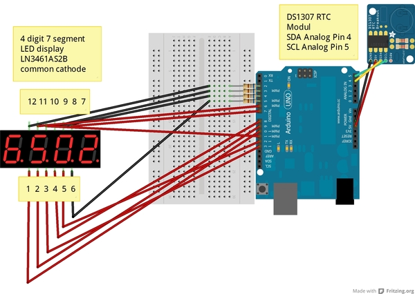
Der Bestückungsplan ist eine Kombination aus dem vorangehenden Projekt und dem RTC-Modul.
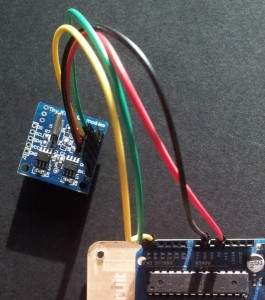
Mein RTC-Modul ist nicht baugleich dem im Bestückungsplan gezeigten von Adafruit, da es noch ein ein Atmel 24C32 Eeprom aufweist. Da das aber im vorliegenden Projekt überhaupt keine Rolle spielt, gilt die gleiche Verkabelung:
- GND zu GND
- VCC zu 5V-Anschluss auf Arduino
- SDA zu analogem Pin A4
- SCL zu analogem Pin A5
Code
Der Code für das LED Display wird etwas einfacher als im Vorprojekt, denn nun entfällt ja die Anzeige von Buchstaben. Dafür kommt ein Teil für das RTC-Modul dazu. Und wenn man die Uhr nicht von der seriellen Schnittstelle aus manuell einstellen möchte (was durchaus möglich ist, wenn man mit einer Ungenauigkeit im Sekundenbereich leben kann), dann lässt sich das auch aus CSharp heraus bewerkstelligen, wie ich es im ersten Uhrenprojekt schon gezeigt habe.
Im CSharp-Projekt wird wie im Projekt „Arduino als Uhr“ der Port in die Konfigurationsdatei ausgelagert:
<?xml version="1.0"?>
<configuration>
    <configSections>
        <sectionGroup name="applicationSettings"
           type="System.Configuration.ApplicationSettingsGroup, System, Version=2.0.0.0, Culture=neutral,
              PublicKeyToken=b77a5c561934e089" >
            <section name="ch.ecotronics.arduino.time.Properties.Settings"
              type="System.Configuration.ClientSettingsSection, System, Version=2.0.0.0, Culture=neutral,
                 PublicKeyToken=b77a5c561934e089" requirePermission="false" />
        </sectionGroup>
    </configSections>
    <startup>

    <supportedRuntime version="v2.0.50727"/></startup>
    <applicationSettings>
        <ch.ecotronics.arduino.time.Properties.Settings>
            <setting name="port" serializeAs="String">
                <value>COM10</value>
            </setting>
        </ch.ecotronics.arduino.time.Properties.Settings>
    </applicationSettings>
</configuration>
Nun also der CSharp-Code zum Einstellen der Uhrzeit:
using System;
using System.IO.Ports;
using System.Configuration;
using ch.ecotronics.arduino.time.Properties;

/*
 * Arduino als Uhr
 * Aktuelle Zeit und Tagesdatum an serielle Schnittstelle senden
 * Autorin: Silvia Rothen, rothen ecotronics, Bern, Switzerland
 * http://ecotronics.ch.honorius.sui-inter.net/wordpress/2013/arduino-als-uhr-version-2-mit-rtc-komponente-und-led-display
 *
 */
namespace ch.ecotronics.arduino.time {
  class ArduinoTimeSetter {

    static void Main(string[] args) {
      Settings settings = new Settings();
      SerialPort port = new SerialPort(settings.port, 9600);
      DateTime now = DateTime.Now;
      port.Open();
      //die Zeit wird für Arduino passend formatiert
      //Achtung neues Format inkl. Wochentag für DS1307
      String arduinoTime = String.Format("{0:HHmmssddMMyy}", DateTime.Now) + ((int) DateTime.Now.DayOfWeek);
      Console.WriteLine(arduinoTime);
      //hier wird die Zeit an die serielle Schnittstelle geschickt
      port.Write(arduinoTime);
      while (true) {
        Console.WriteLine("From Arduino " + port.ReadLine());
      }
    }
  }
}
Die Kommunikation mit der RTC erfolgt über I2C, deshalb muss die Library Wire eingebunden werden. Und nun der vollständige Arduino-Code:
  //Arduino 1.0+ Only
//Funktioniert zusammen mit C:\dateienmitback\dropbox\arduino\_doku\csharp\ConsoleApplication1\ConsoleApplication1\
//Quellen u.a.
// http://ur5uppe.blogspot.ch/2012/05/arduino-und-rtc-real-time-clock.html

#include "Wire.h"
#define DS1307_ADDRESS 0x68

boolean DigitOn = LOW;
boolean DigitOff = HIGH;
boolean SegOn=HIGH;
boolean SegOff=LOW;
int DigitPins[] = {2, 3, 4, 5};
int SegmentPins[] = {6, 7, 8, 9, 10, 11, 12, 13};

int BLANK[] = {LOW, LOW, LOW, LOW, LOW, LOW, LOW, LOW};
int N0[]    = {HIGH, HIGH, HIGH, HIGH, HIGH, HIGH, LOW, LOW};
int N0P[]   = {HIGH, HIGH, HIGH, HIGH, HIGH, HIGH, LOW, HIGH};
int N1[]    = {LOW, HIGH, HIGH, LOW, LOW, LOW, LOW, LOW};
int N1P[]   = {LOW, HIGH, HIGH, LOW, LOW, LOW, LOW, HIGH};
int N2[]    = {HIGH, HIGH, LOW, HIGH, HIGH, LOW, HIGH, LOW};
int N2P[]   = {HIGH, HIGH, LOW, HIGH, HIGH, LOW, HIGH, HIGH};
int N3[]    = {HIGH, HIGH, HIGH, HIGH, LOW, LOW, HIGH, LOW};
int N3P[]   = {HIGH, HIGH, HIGH, HIGH, LOW, LOW, HIGH, HIGH};
int N4[]    = {LOW, HIGH, HIGH, LOW, LOW, HIGH, HIGH, LOW};
int N4P[]   = {LOW, HIGH, HIGH, LOW, LOW, HIGH, HIGH, HIGH};
int N5[]    = {HIGH, LOW, HIGH, HIGH, LOW, HIGH, HIGH, LOW};
int N5P[]   = {HIGH, LOW, HIGH, HIGH, LOW, HIGH, HIGH, HIGH};
int N6[]    = {HIGH, LOW, HIGH, HIGH, HIGH, HIGH, HIGH, LOW};
int N6P[]   = {HIGH, LOW, HIGH, HIGH, HIGH, HIGH, HIGH, HIGH};
int N7[]    = {HIGH, HIGH, HIGH, LOW, LOW, LOW, LOW, LOW};
int N7P[]   = {HIGH, HIGH, HIGH, LOW, LOW, LOW, LOW, HIGH};
int N8[]    = {HIGH, HIGH, HIGH, HIGH, HIGH, HIGH, HIGH, LOW};
int N8P[]   = {HIGH, HIGH, HIGH, HIGH, HIGH, HIGH, HIGH, HIGH};
int N9[]    = {HIGH, HIGH, HIGH, HIGH, LOW, HIGH, HIGH, LOW};
int N9P[]   = {HIGH, HIGH, HIGH, HIGH, LOW, HIGH, HIGH, HIGH};

byte zero = 0x00; //workaround for issue #527
char incoming[14] = {}; //wegen Endzeichen
char time[6] = {};
int* lights[4];
int tmp[8];

void setup(){
  Wire.begin();
  Serial.begin(9600);
  for (byte digit=0;digit<4;digit++) {
    pinMode(DigitPins[digit], OUTPUT);
  }
  for (byte seg=0;seg<8;seg++) {
    pinMode(SegmentPins[seg], OUTPUT);
  }
  //initialize display with 1.234
  lights[0] = N1P;
  lights[1] = N2;
  lights[2] = N3;
  lights[3] = N4;
}

void loop(){
  setDateTime(); //MUST CONFIGURE IN FUNCTION
  printDate();
  Serial.print("Hour2 ");
  Serial.println(time);
    int counter = -1;
    for (int tmp = 0; tmp < 5; tmp++) {
      counter++;
      switch(time[tmp]){
        case '0':
          if (tmp  < 8 && (time[tmp + 1] == '.' || time[tmp + 1] == ',')) {
            lights[counter] = N0P;
            tmp++;
          } else {
            lights[counter] = N0;
          }
          break;
        case '1':
          if (tmp  < 8 && (time[tmp + 1] == '.' || time[tmp + 1] == ',')) {
            lights[counter] = N1P;
            tmp++;
          } else {
            lights[counter] = N1;
          }
          break;
        case '2':
          if (tmp  < 8 && (time[tmp + 1] == '.' || time[tmp + 1] == ',')) {
            lights[counter] = N2P;
            tmp++;
          } else {
            lights[counter] = N2;
          }
          break;
        case '3':
          if (tmp  < 8 && (time[tmp + 1] == '.' || time[tmp + 1] == ',')) {
            lights[counter] = N3P;
            tmp++;
          } else {
            lights[counter] = N3;
          }
          break;
        case '4':
          if (tmp  < 8 && (time[tmp + 1] == '.' || time[tmp + 1] == ',')) {
            lights[counter] = N4P;
            tmp++;
          } else {
            lights[counter] = N4;
          }
          break;
        case '5':
          if (tmp  < 8 && (time[tmp + 1] == '.' || time[tmp + 1] == ',')) {
            lights[counter] = N5P;
            tmp++;
          } else {
            lights[counter] = N5;
          }
          break;
        case '6':
          if (tmp  < 8 && (time[tmp + 1] == '.' || time[tmp + 1] == ',')) {
            lights[counter] = N6P;
            tmp++;
          } else {
            lights[counter] = N6;
          }
          break;
        case '7':
          if (tmp  < 8 && (time[tmp + 1] == '.' || time[tmp + 1] == ',')) {
            lights[counter] = N7P;
            tmp++;
          } else {
            lights[counter] = N7;
          }
          break;
        case '8':
          if (tmp  < 8 && (time[tmp + 1] == '.' || time[tmp + 1] == ',')) {
            lights[counter] = N8P;
            tmp++;
          } else {
            lights[counter] = N8;
          }
          break;
        case '9':
          if (tmp  < 8 && (time[tmp + 1] == '.' || time[tmp + 1] == ',')) {
            lights[counter] = N9P;
            tmp++;
          } else {
            lights[counter] = N9;
          }
          break;

        default: lights[counter] = BLANK;
      }
    } //end for

  //This part of the code is from the library SevSeg by Dean Reading
  for (byte seg=0;seg<8;seg++) {
    //Turn the relevant segment on
    digitalWrite(SegmentPins[seg],SegOn);

    //For each digit, turn relevant digits on
    for (byte digit=0;digit<4;digit++){
      if (lights[digit][seg]==1) {
        digitalWrite(DigitPins[digit],DigitOn);
      }
      //delay(200); //Uncomment this to see it in slow motion
    }
    //Turn all digits off
    for (byte digit=0;digit<4;digit++){
      digitalWrite(DigitPins[digit],DigitOff);
    }

    //Turn the relevant segment off
    digitalWrite(SegmentPins[seg],SegOff);
  } //end of for
    //delay(1000);
}

void setDateTime(){
  if (Serial.available() > 0) {
    int i = 0;
    //Array of Char leeren
    memset(incoming, 0, sizeof(incoming));
    //Zeit wird geliefert als HHmmssddMMyyw, z.B. 1329002001137
    //letzte Ziffer Wochentag von 0 Sonntag bis 6 Samstag
    while (Serial.available() > 0 && i < sizeof(incoming) - 1) {
      incoming[i] = Serial.read();
      i++;
      delay(3);
    }

    //in Zeit umwandeln
    char hr[3] = {};
    char min[3] = {};
    char sec[3] = {};
    char day[3] = {};
    char month[3] = {};
    char yr[3] = {};
    char wochentag[2] = {};
    hr[0] = incoming[0];
    hr[1] = incoming[1];
    min[0] = incoming[2];
    min[1] = incoming[3];
    sec[0] = incoming[4];
    sec[1] = incoming[5];
    day[0] = incoming[6];
    day[1] = incoming[7];
    month[0] = incoming[8];
    month[1] = incoming[9];
    yr[0] = incoming[10];
    yr[1] = incoming[11];
    wochentag[0] = incoming[12];

    Serial.print("Neues Datum ");
    printDigits(atoi(day), "");
    printDigits(atoi(month), ".");
    printDigits(atoi(yr), ".");
    Serial.println("");
    byte second =      atoi(sec); //0-59
    byte minute =      atoi(min); //0-59
    byte hour =        atoi(hr); //0-23
    byte weekDay =     atoi(wochentag); //0-6 -> sunday - Saturday
    byte monthDay =    atoi(day); //1-31
    byte monthb =       atoi(month); //1-12
    byte year  =       atoi(yr); //0-99

    Wire.beginTransmission(DS1307_ADDRESS);
    Wire.write(zero); //stop Oscillator

    Wire.write(decToBcd(second));
    Wire.write(decToBcd(minute));
    Wire.write(decToBcd(hour));
    Wire.write(decToBcd(weekDay));
    Wire.write(decToBcd(monthDay));
    Wire.write(decToBcd(monthb));
    Wire.write(decToBcd(year));

    Wire.write(zero); //start

    Wire.endTransmission();
  }
}

byte decToBcd(byte val){
// Convert normal decimal numbers to binary coded decimal
  return ( (val/10*16) + (val%10) );
}

byte bcdToDec(byte val)  {
// Convert binary coded decimal to normal decimal numbers
  return ( (val/16*10) + (val%16) );
}


void printDate(){

  // Reset the register pointer
  Wire.beginTransmission(DS1307_ADDRESS);
  Wire.write(zero);
  Wire.endTransmission();

  Wire.requestFrom(DS1307_ADDRESS, 7);

  int second = bcdToDec(Wire.read());
  int minute = bcdToDec(Wire.read());
  int hour = bcdToDec(Wire.read() & 0b111111); //24 hour time
  int weekDay = bcdToDec(Wire.read()); //0-6 -> sunday - Saturday
  int monthDay = bcdToDec(Wire.read());
  int month = bcdToDec(Wire.read());
  int year = bcdToDec(Wire.read());
  String strTime = "";

  if (hour < 10) {
    strTime += "0";
    strTime += hour;
    strTime += ".";
  } else {
    strTime += "";
    strTime += hour;
    strTime += ".";
  }

  if (minute < 10) {
    strTime = strTime + "0" + minute;
  } else {
    strTime = strTime + minute;
  }

  strTime.toCharArray(time, 6);
}

void printDigits(int digits, char trennzeichen[2] ){
  // Hilfsfunktion zur Datums-/Zeitdarstellung:
  //Gibt vorstehenden Doppelpunkt und führende 0 aus
  Serial.print(trennzeichen);
  if(digits < 10) {
    Serial.print('0');
  }
  Serial.print(digits);
}

void returnSegments(int number, int *tmp) {
  if (number == 1) {
    tmp = N1;
  }
}
Demo
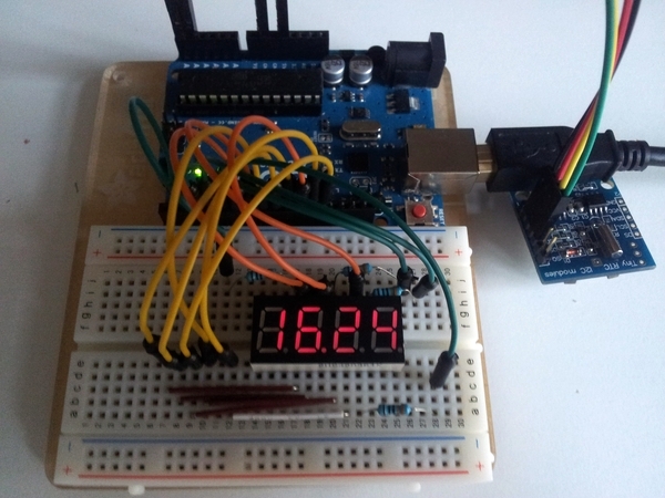
Im Bild sieht man die ganze Installation mit Arduino, LED Display und RTC-Modul:


 Download des Artikels als PDF File